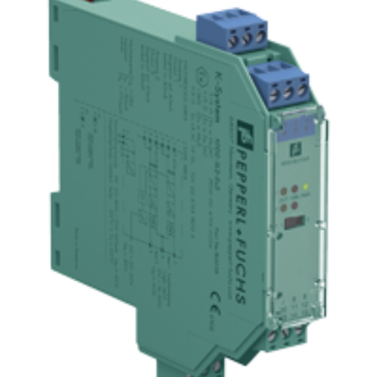
參數(shù)表節(jié)選:的技術參數(shù) KCD2-UT2-1
| General specifications | ||
|---|---|---|
| Signal type | Analog input | |
| Functional safety related parameters | ||
| Safety Integrity Level (SIL) | SIL 2 | |
| Supply | ||
| Connection | terminals 9+, 10- or power feed module/Power Rail | |
| Rated voltage | 19 ... 30 V DC | |
| Ripple | within the supply tolerance | |
| Power dissipation | ≤ 0.98 W | |
| Power consumption | max. 0.98 W | |
| Interface | ||
| Programming interface | programming socket | |
| Input | ||
| Connection side | field side | |
| Connection | terminals 1, 2, 3, 4 | |
| RTD | type Pt10, Pt50, Pt100, Pt500, Pt1000 (EN 60751: 1995) type Pt10GOST, Pt50GOST, Pt100GOST, Pt500GOST, Pt1000GOST (6651-94) type Cu10, Cu50, Cu100 (P50353-92) type Ni100 (DIN 43760) | |
| Measuring current | approx. 200 μA with RTD | |
| Types of measuring | 2-, 3-, 4-wire connection | |
| Lead resistance | max. 50 Ω per line | |
| Measurement loop monitoring | sensor breakage, sensor short-circuit | |
| Thermocouples | type B, E, J, K, N, R, S, T (IEC 584-1: 1995) type L (DIN 43710: 1985) type TXK, TXKH, TXA (P8.585-2001) | |
| Cold junction compensation | external and internal | |
| Measurement loop monitoring | sensor breakage | |
| Potentiometer | 0 ... 20 kΩ (2-wire connection), 0.8 ... 20 kΩ (3-wire connection) | |
| Voltage | selectable within the range -100 ... 100 mV | |
| Input resistance | ≥ 1 MΩ (-100 ... 100 mV) | |
| Output | ||
| Connection side | control side | |
| Connection | terminal 5: source (-), terminal 6: source (+), terminal 7: sink(-), terminal 8: sink (+) | |
| Output | Analog current output | |
| Current range | 0 ... 20 mA or 4 ... 20 mA | |
| Fault signal | downscale 0 or 2 mA, upscale 21.5 mA (acc. NAMUR NE43) | |
| Source | load 0 ... 550 Ω open-circuit voltage ≤ 18 V | |
| Sink | Voltage across terminals 5 ... 30 V. If the current is supplied from a source > 16.5 V, series resistance of ≥ (V - 16.5)/0.0215 Ω is needed, where V is the source voltage. The maximum value of the resistance is (V - 5)/0.0215 Ω. | |
| Transfer characteristics | ||
| Deviation | ||
| After calibration | Pt100: ± (0.06 % of measurement value in K + 0.1 % of span + 0.1 K (4-wire connection)) thermocouple: ± (0.05 % of measurement value in °C + 0.1 % of span + 1.5 K (1.7 K for types R and S)) , includes ± 1.3 K fault of the cold junction compensation (CJC) mV: ± (50 μV + 0.1 % of span) potentiometer: ± (0.05 % of full scale + 0.1 % of span, (excludes faults due to lead resistance)) | |
| Influence of ambient temperature | Pt100: ± (0.0015 % of measurement value in K + 0.006 % of span)/K ΔTamb*) thermocouple: ± (0.02 K + 0.005 % of measurement value in °C + 0.006 % of span)/K ΔTamb*)), influence of cold junction compensation (CJC) included mV: ± (0.01 % of measurement value + 0.006 % of span)/K ΔTamb*) potentiometer: ± 0.006 % of span/K ΔTamb*) *) ΔTamb = ambient temperature change referenced to 23 °C (296 K) | |
| Influence of supply voltage | < 0.01 % of span | |
| Influence of load | ≤ 0.001 % of output value per 100 Ω | |
| Reaction time | worst case value (sensor breakage and/or sensor short circuit detection enabled) mV: 1 s, thermocouples with CJC: 1.1 s, thermocouples with fixed reference temperature: 1.1 s, 3- or 4-wire RTD: 920 ms, 2-wire RTD: 800 ms, Potentiometer: 2.05 s | |